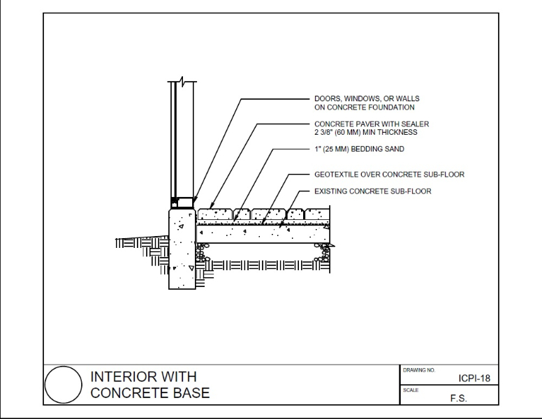
Component drawings might describe units such as. Individual components identified with balloons and leader lines.
 Watch Movement Diagram Mechanical Watch Movement Construction Esslinger And Company Watch Drawing Watch Movement Mechanical Watch
A component diagram also known as a UML component diagram describes the organization and wiring of the physical components in a system.
Define component drawings. Enough orthogonal views. They show how the components fit together and may include orthogonal plans sections and elevations or three-dimensional views showing the assembled components or an exploded view showing the relationship between the components and how they fit together. The items these drawings should specify are.
An engineering drawing is a type of technical drawing that is used to convey information about an object. 38 1 Read as 38 inch on the drawing equals 1 foot on the actual component or system. Producing Drawing A component or part drawing is termed as a production drawing if it facilities its manufacture.
The detail drawing conveys as much information as possible about a single component. Drawing is the actual distance or size of the component. Drawings and Specifications means i all specifications calculations design plans drawings engineering and analyses and other documents which determine establish define or otherwise describe the scope quantity and relationship of the components of the Project and ii all technical drawings operating drawings specifications shop drawings diagrams illustrations schedules and.
The Detail Drawing. Shop drawings depict a range of prefabricated componentsfrom steel beams trusses and concrete panels to elevators appliances cabinetry ductwork and electrical layouts. Assembly drawings can be used to represent items that consist of more than one component.
Detail drawings sometimes called manufacturing drawings usually show a single component and give all the information necessary for the manufacture of that component. For example if a component part measures 68 inch on the drawing the actual component measures 2 feet. It will be clearly labeled with a part number and name It may include several views of the object--top front and side--and a projection view.
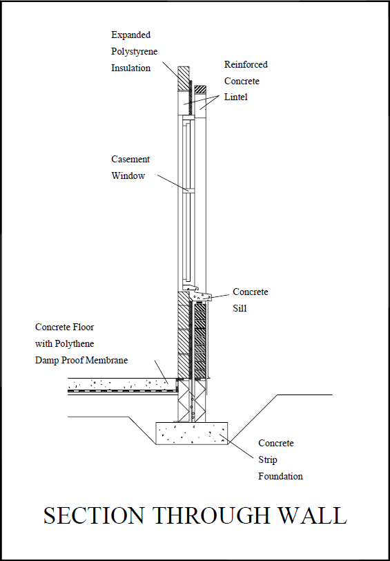
Must be evenly distributed structured and not duplicated. The form or shape of the component Full dimensions tolerances and surface finish. Beams windows doors sills coping stones and so on.
This is called 38 scale. Enough views to adequate describe the component. Usually a number of drawings are necessary to completely specify even a simple component.
These diagrams are also used as a communication tool between the developer and stakeholders of the system. 12 1 Read as 12 inch on the drawing equals 1 foot on the actual. A component may be defined as any item used in a building which emanates from a single source of supply and which arrives on site as a complete and self-contained unit whose incorporation into the building requires only its fixing to another.
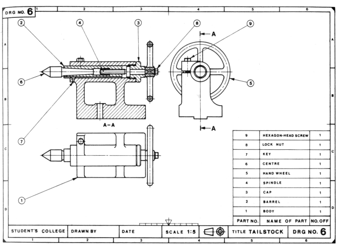
You want the name to be specific enough that you can easily locate the component in the Outliner among your other geometry. Assembly Drawings must have a number of views to show how parts fit together. A common use is to specify the geometry necessary for the construction of a component and is called a detail drawing.
110 15 12 11 and so on. Detail Drawings must provide sufficient information to enable the manufacture a part. In this method the object is placed in space in such a way that the front view of it is captured in the vertical plane and the top view of the same is captured in the horizontal plane.
The Create Component dialog box appears. They may be drawn at large scales such as. A component diagram allows verification that a systems required functionality is acceptable.
Dimensions to indicate range of motion or overall size of assembly for reference purposes. Section views to show how parts fit and to eliminate hidden detail. Component drawings provide detailed information about the individual units.
It furnishes all dimensions limits and special finishing processes such as heat treatment grinding etc in. Component diagrams are often drawn to help model implementation details and double-check that every aspect of the systems required functions is covered by planned development. While the interpretation of a component in terms of sketching can be done in various methods related to Descriptive Geometry the three most necessary techniques of drawingprojection are.
Drawing must state the scale used to fit the component onto the drawing sheet. The drawings are linked together by a master drawing or assembly drawing which gives. In the Definition box type a meaningful name for your component.
The architectural and engineering manufacturing business is a huge one. It is an authorized document to produce the component in the shop floor. If you are designing or planning a prefabricated component for an AEC program you typically need a shop drawing to ensure that the component is professionally fabricated and installed to industry.
They always produce a lot of specifications for pre-fabricated components such as elevators structural steel trusses pre-cast cabinets windows appliances etc. Choose Edit Make Component from the menu bar or context-click the selection and choose Make Component. These are called shop drawing.
 Below In Figure Qi Is An Isometric Drawing Of A Chegg Com Isometric Drawing Autocad Isometric Drawing Isometric
 Adaptive Skins Parametric Design Workshop Report Parametric Design Parametric Parametric Architecture
What Are Detail And Assembly Drawings Youtube
 Pin On Tech Drawings
 Practical Composition Part 7 Organizing Figures Cool Drawings Figures Learning
 Gesture Hand Drawings By Architects Design Milk Architecture Design Sketch Architect Drawing Architecture Sketch
 Pin On Mechanical Engineering
 Pin By Nadja Elpis On Architecture In 2021 Green Wall Detailed Drawings Wall Paneling
 Drawing For The Absolute Beginner A Clear Easy Guide To Successful Drawing Absolute Beginners Drawings Basic Shapes
 Mechanical Engineering Solution Mechanical Engineering Design Technical Drawing Mechanical Engineering
 Unique Define Pictorial Drawing Diagram Wiringdiagram Diagramming Diagramm Visuals Visualisation Graphical Technical Drawing Diagram Drawings
 Unique Define Pictorial Drawing Diagram Wiringdiagram Diagramming Diagramm Visuals Visualisation Graphical Drill Bit Sizes Drill Bits Drill
 Component Drawing Designing Buildings Wiki
 Machine Drawing Sleeve And Cotter Joint Socket And Spigot Joint And Knuckle Joint Geometric Drawing Autocad Drawing Drawings
 Assembly Drawing Designing Buildings Wiki
 Options Building Information Modeling Bim Revit Tutorial
 Detail Drawing Designing Buildings Wiki
 Pin By Lizbet Nundy On Art Tips Spongebob Drawings Comic Tutorial Comic Drawing
 Pin Di Desain Pondasi


0 Komentar