By default ports are public however UML 20 allows you to have internal ports that are available only to. UML is a set of conventions for object-oriented diagrams that has a wide variety of applications.

Exposing the functionality through a port allows the subsystem to be used by any other classifier that conforms to the ports specifications.

Define component port and connectors in uml. A short answer first trying to rip up the rest later. UML the Unified Modeling Language is a standard that has wide. UML Component Diagram library contains 36 shapes Port.
Definition of the components. The internal view shows how external behavior is realized internally. To learn more about UML and its uses check out our guide What Is UML.
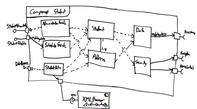
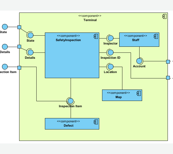
UML 2x component diagram. Janis Osis Uldis Donins in Topological UML Modeling 2017 1214 Component Diagram A component diagram shows the internal parts connectors and ports that implement a component. The lines between components are often referred to as connectors the implication being that some sort of messaging will occur across the connectors.
This allows one component to provide the services that another component requires. Now for the details. And connectors with roles to define how they can be bound to ports.
A port is an embedded element which allows to group a number of interfaces. A Yes thats correct. UML Component Diagram illustrates show components are wired together to larger components and software systems that shows the structure of arbitrarily complex systems.
It shows the internal structure including parts and connectors of a structured classifier or collaboration. Solid line no arrow. Dashed line open arrow.
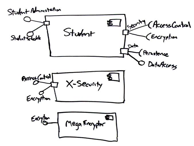
A component has an external view with public properties and operations and it has an internal view with private properties and realizing classifiers. Customers component part provides Account interface to Orders part. The components and connectors are bound together to.
I found that these four resources draw connectors in different way. Code generation from UML well defined for OO concepts Define generation for component concepts Ports internal code inside and external API Connections assembly and delegation Existing CCM mapping CIF not only suitable solution Robotic middleware Orocosmaps all ports consuming data to a. UML component diagrams describe software components and their dependencies to each others A component is an autonomous unit within a system The components can be used to define software systems of arbitrary size and complexity.
Making a comparison to natural languages if the elements are nouns the connectors are verbs that describe how the nouns relate to each other. When the component is instantiated copies of its internal parts are also instantiated. The option fill assembly connector sets the colors of the assembly connector symbol whereas the option fill port sets the colors of the port symbol.
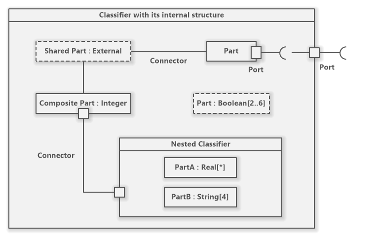
The best I can come up for an example is a complex socket the port which bundles things like power supply communication lines you name it the interfaces. A composite structure diagram is a UML structural diagram that contains classes interfaces packages and their relationships and that provides a logical view of all or part of a software system. Diagrams such as Figure 1 are often referred to as wiring diagrams because they show how the various software components are wired together to build your overall application.
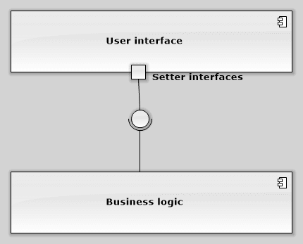
The assembly connector bridges a components required interface Component1 with the provided interface of another component Component2. Connector originating in a required port and delivered to a provided port. Connectors link elements together and are typically represented as lines on diagrams showing how the elements relate to each other.
To design a Component Diagram use the UML Component Diagram library. Rapid UML Solution for ConceptDraw DIAGRAM contains 13 vector stencils libraries with 393 interactive shapes that you can use to design your UML diagrams. Components in UML could represent logical components eg business components process components and physical components eg CORBA components EJB components COM andNET components WSDL components etc along with the artifacts that implement them and the nodes on which they are deployed and executed.
The UML has a wide variety of connector types that are used. Starting with UML 20 classes have been extended to allow for ports and internal structures. Simple ports joined directly by connector mandatory UML notation.
A component in UML represents a modular part of a system. Solid line open arrow delegate stereotype. Component port connector role component functionality port protocol connector protocol role protocol Relations component decomposition port-role binding for.
Solid line open arrow delegate stereotype. There is 6 components A D E F G and H and 2 sub-components of A. The behavior is defined in terms of required and provided interfaces.
As an option UML allows connector line to be attached to the ball and socket instead of ports as shown below. In component diagrams the Unified Modeling Language dictates that components and packages are wired together with lines representing assembly connectors and delegation connectors. UML 1x component diagram.
Section about component diagram on uml-diagrams. 671 Example from introduction step by step.
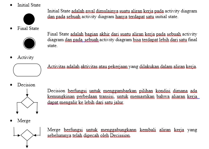 Uml Diagram Activity Diagram
 Component Diagram Uml 2 Diagrams Uml Modeling Tool

 The Logging Aspect Model Using A Uml Collaboration Stereotype Download Scientific Diagram
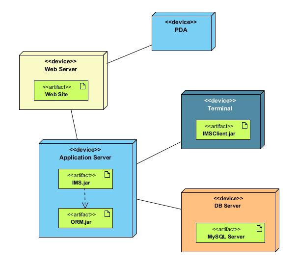 Deployment Diagram Uml 2 Diagrams Uml Modeling Tool
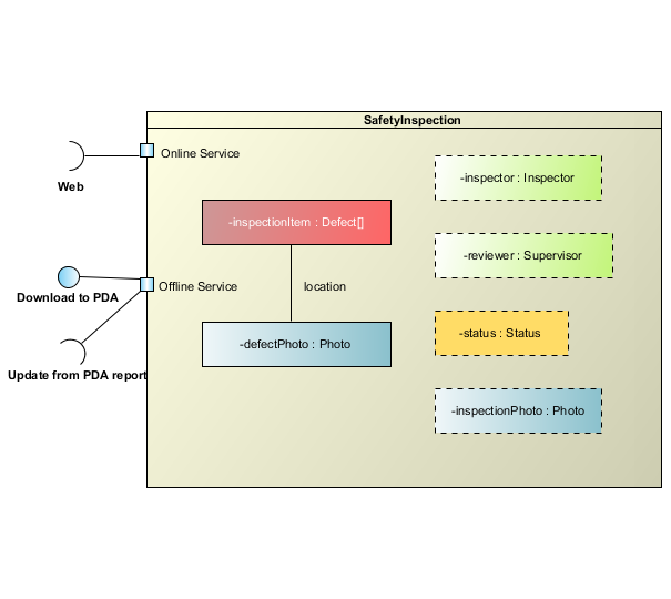
Uml Composite Structure Diagram Tutorial Software Ideas Modeler
 Uml Dependency Between Interfaces In Provided Required Notation Stack Overflow
 Composite Structure Diagram Uml 2 Diagrams Uml Modeling Tool
 1 Uml Class Diagram Of The Distribution Aspect For Bluetooth In Download Scientific Diagram
 Uml Composite Structure Diagram Tutorial Software Ideas Modeler
 A Uml Diagram Providing A High Level Overview Of The P2p Reference Download Scientific Diagram
 Using Uml Patterns And Java Objectoriented Software Engineering
 Bookstore Management System Infrastructure Management Services Invoice Format In Excel Use Case
 Deal With Component Diagram Uml 2 0 Come As You Are
 Uml Diagram Activity Diagram
Example Of A Uml Class Diagram Download Scientific Diagram


0 Komentar