In order to mix interface and component or deployment element you must use the long description with or long string then we observe the expected result. In a configuration file provided in the command line or the Ant task.
 Uml Component Diagram Javatpoint
One component may therefore be substituted by another only if the two are.

Define component diagram. A component diagram also known as a UML component diagram describes the organization and wiring of the physical components in a system. Flows that transport data around the data flow diagram are called data flows. In an included file.
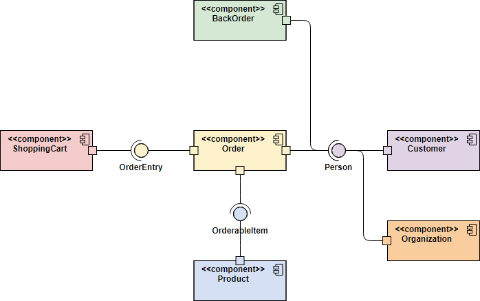
What is a Component Diagram. The Component Diagram helps to model the physical aspect of an Object-Oriented software system. In the diagram definition like any other commands.
It illustrates the architectures of the software components and the dependencies between them. UML is a set of conventions for object-oriented diagrams that has a. Component diagrams can describe software systems that are implemented in any programming language or style.
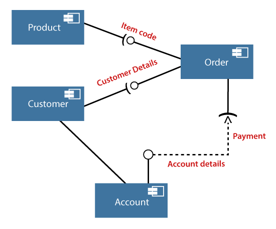
A component diagram shows the internal parts connectors and ports that implement a component. Graphically a component diagram is a collection of vertices and arcs and commonly contain components interfaces and dependency aggregation constraint generalization association and realization relationships. A component flow diagram is a type of UML diagram that illustrates and defines the overall components that are part of a composite software system.
Startuml interface Interf4 Last interface String data void methods component C database D C - Interf4 Interf4 - D enduml. Description of Data Flows. Component serves as a type whose conformance is defined by these provided and required interfaces encompassing both their static as well as dynamic semantics.
When the component is instantiated copies of its internal parts are also instantiated. A Component diagram illustrates the pieces of software embedded controllers and such that make up a system and their organization and dependencies. You can define specific color and.
It may also contain notes and constraints. Component diagrams are often drawn to help model implementation details and double-check that every aspect of the systems required functions is covered by planned development. Or a hardware component such as a circuit microchip or device.
Data flows are the pipelines through which data are transmitted between any two components on a DFD. This diagram defines the architectural structure of the entire system in terms of the components and how they are interconnected. Those software components including run-time components executable components also the source code components.
The difference between package diagrams and component diagrams is that Component Diagrams offer a more semantically rich grouping mechanism. Flows define the interfaces between the components within the system and the system and its external components. Components are similar in practice to package diagrams as they define boundaries and are used to group elements into logical structures.
Component diagrams are used to visualize the organization of system components and the dependency relationships between them. The components can be a software component such as a database or user interface. Or a business unit such as supplier.
A Component diagram has a higher level of abstraction than a Class diagram. They provide a high-level view of the components within a system. Usually a component is implemented by one or more Classes or Objects at runtime.
 Use Case Diagram Relationships Explained With Examples Creately Blog Use Case Diagram Online Diagram
 Componentdiagram Software Architecture Diagram Resume Template Free Enterprise Architecture
King Chess Game Design Components Diagram Component Diagram Game Design Diagram
 Uml Class Diagram For Online Food Ordering System You Can Modify This According To The System Structure Of Your En Class Diagram Online Food Data Flow Diagram
 What Is Unified Modeling Language Uml Class Diagram State Diagram Solution Architect
 Uml Introduction Draft Activity Diagram State Diagram Data Flow Diagram
 Bpm Tutorial Business Process Modeling Guide Include Methodologies Business Process Business Process Management School Motivation College
 Uml Diagram Types Learn About All 14 Types Of Uml Diagrams Diagram Communication Tutorial
 The Ultimate Class Diagram Tutorial To Help Model Your Systems Easily Class Diagram Tutorial Diagram
 22 References Of Uml Network Diagram Examples Design Http Bookingritzcarlton Info 22 References Of Uml Relationship Diagram Data Flow Diagram Class Diagram
 The Ultimate Class Diagram Tutorial To Help Model Your Systems Easily Class Diagram Tutorial Diagram
 The Ultimate Class Diagram Tutorial To Help Model Your Systems Easily Class Diagram Tutorial Pattern Design
 The Ultimate Class Diagram Tutorial To Help Model Your Systems Easily Class Diagram Tutorial Diagram
 An Entity Relationship Diagram Showing A Structured Approach To Defining A Metadata Schema Courtes Relationship Diagram Information Architecture Class Diagram
 Component Diagram Tutorial
 Design Patterns For Software Strategy Class Diagram Uml Class Diagram Pattern Design Strategies
 Uml Class Diagram Example School Management System Class Diagram Template Class Diagram School Management Student Information
 Archer Tower Printable Diagram Source Class Diagram Sequence Diagram Diagram
 The Ultimate Class Diagram Tutorial To Help Model Your Systems Easily Class Diagram Tutorial Diagram


0 Komentar